
An article to understand the difference between stepper motors and servos and servo motors
2025-04-02
I. Differences between stepper motors and servos and servo motors
Stepper motor: is the electrical pulse signal into angular displacement or line displacement of the open-loop control element stepper motor parts. Simply put, it relies on the electrical pulse signal to control the angle and the number of turns. So he only rely on the pulse signal to determine how much rotation. Since there is no sensor, the stopping angle may deviate. However, the precise pulse signal minimizes the deviation.
Servo motor: rely on the servo control circuit to control the speed of the motor, through the sensor to control the rotation position. So the position control is very precise. And the rotational speed is also variable.
Servo (Electronic Servo): The main component of the servo is the servo motor. It contains servo motor control circuit + reduction gear set. Oh yeah, servo motor doesn't have reduction gear set. And the servo has a reduction gear set.
In the case of a limit servo, it relies on a potentiometer under the output shaft to determine the steering angle of the rudder arm. The servo signal control is a pulse width modulated (PWM) signal, where a microcontroller can easily generate this signal.
II. Stepper motor basic principle
How it works:
Normally the rotor of a motor is a permanent magnet, and when current flows through the stator windings, the stator windings produce a vector magnetic field. This magnetic field will drive the rotor to rotate by an angle, so that the direction of the pair of magnetic fields of the rotor will be the same as the direction of the magnetic field of the stator. When the vector magnetic field of the stator rotates by an angle. The rotor also rotates by an angle with this magnetic field. For each input electrical pulse, the motor rotates one angular step forward. Its output angular displacement is proportional to the number of input pulses, and its rotational speed is proportional to the frequency of the pulses. By changing the order in which the windings are energized, the motor reverses. Therefore, the number and frequency of pulses and the order of energizing the windings of each phase of the motor can be controlled to control the rotation of the stepper motor.
Principle of heat generation:
Usually see all kinds of motors, internal are iron core and winding coil. Winding resistance, power will produce loss, loss size and resistance and current is proportional to the square, which is often referred to as copper loss, if the current is not the standard DC or sine wave, will also produce harmonic loss; core has hysteresis eddy current effect, in the alternating magnetic field will also produce loss, the size of the material, current, frequency, voltage related, which is called iron loss. Copper loss and iron loss will be manifested in the form of heat generation, thus affecting the efficiency of the motor. Stepping motor generally pursue positioning accuracy and torque output, efficiency is relatively low, the current is generally larger, and the harmonic components are high, the frequency of the current alternating with the speed and change, so stepping motors generally have a heat situation, and the situation is more serious than the general AC motor.
III. Rudder construction
The servo is mainly composed of a housing, a circuit board, a drive motor, a gear reducer and a position detection element. Its working principle is that the receiver sends a signal to the servo, and the IC on the circuit board drives the coreless motor to start rotating, and the power is transmitted to the swing arm through the reduction gear, and at the same time, the position detector sends a signal back to determine whether it has arrived at the positioning or not. The position detector is actually a variable resistor. When the servo rotates, the resistor value will change accordingly, and the angle of rotation can be known by detecting the resistor value. General servo motor is a thin copper wire wrapped around a three-pole rotor, when the current flows through the coil will generate a magnetic field, and the periphery of the rotor magnet to produce repulsion, which in turn generates the force of rotation. According to physics, the moment of inertia of an object is directly proportional to its mass, so the greater the mass of the object to be rotated, the greater the force required. In order to achieve fast rotation speed and low power consumption, the servo is made of thin copper wires twisted into a very thin hollow cylinder, forming a very lightweight hollow rotor with no poles, and magnets are placed inside the cylinder, which is the hollow cup motor.
In order to suit different working environments, there are servos with waterproof and dustproof designs; and in response to different load requirements, there are plastic and metal gears for servos, and metal gears for servos are generally high-torque and high-speed, with the advantage that the gears will not be chipped due to excessive loads. Higher grade servos will be equipped with ball bearings to make the rotation faster and more accurate. There is a difference between one ball bearing and two ball bearings, of course the two ball bearings are better. The new FET servos are mainly using FET (Field Effect Transistor), which has the advantage of low internal resistance and therefore less current loss than normal transistors.
IV. Servo principle of operation
From the pwm wave into the internal circuit to generate a bias voltage, the contactor generator through the reduction gear to drive the potentiometer to move, so that when the voltage difference is zero, the motor stops, so as to achieve the effect of servo.
The protocols for servo PWMs are all the same, but the latest servos to appear may be different.
The protocol is generally: high level width in 0.5ms ~ 2.5ms to control the servo to turn through different angles.
V. How servo motors work
The figure below shows a servo motor control circuit made with a power operational amplifier LM675, and the motor is a DC servo motor. As can be seen from the figure, the power operational amplifier LM675 is supplied by 15V, and the 15V voltage is added to the in-phase input of the operational amplifier LM675 through RP 1, and the output voltage of the LM675 is added to the input of the servo motor. The motor is equipped with a speed measurement signal generator for real-time detection of the motor speed. In fact, the speed signal generator is a kind of generator, and its output voltage is proportional to the rotational speed. The voltage output from the speed measuring signal generator G is fed back to the inverting input of the operational amplifier as a speed error signal after a voltage divider circuit. The voltage value set by the speed command potentiometer RP1 is added to the in-phase input of the operational amplifier after voltage division by R1.R2, which is equivalent to the reference voltage.
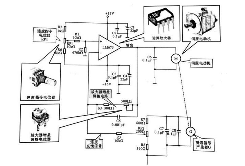
Control schematic of servo motor
Servomotor: Indicated by the letter M for servomotor, it is the source of power for the drive system. Operational amplifier: denoted by the circuit name, i.e., LM675, is an amplifier piece in the servo control circuit that provides the drive current for the servo motor.
Speed command potentiometer RP1: Sets the reference voltage of the operational amplifier in the circuit, i.e. speed setting. Amplifier gain adjustment potentiometer RP2: Used in the circuit to fine-tune the amplifier gain and the size of the speed feedback signal, respectively.
When the load of the motor changes, the voltage fed back to the inverted input of the operational amplifier also changes, i.e., when the load of the motor is increased, the speed decreases, and the output voltage of the speed signal generator also decreases, so that the voltage at the inverted input of the operational amplifier decreases, and the difference between this voltage and the reference voltage increases, and the output voltage of the operational amplifier increases. Conversely, when the load becomes smaller and the motor speed increases, the output voltage of the speed measuring signal generator rises, the feedback voltage added to the inverted input of the operational amplifier increases, the difference between this voltage and the reference voltage decreases, the output voltage of the operational amplifier decreases, and the motor speed decreases accordingly, so that the rotational speed can be stabilized at the set value automatically.