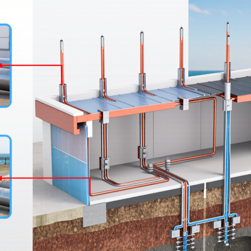
Air terminal
(solid copper) | Solid copper with suitable mechanical strength and corrosion resistance. | Minimum diameter: 3/8 in (9.5 mm) for a commonly specified solid round copper air terminal. | Use an air terminal with a height and spacing arrangement that protects the exposed roof area and connected objects. | Use a component evaluated for lightning protection service and install it according to its listing and installation requirements. | Suitable for many copper-based systems. Check contact compatibility when connecting to aluminum components. |
Air terminal
(solid aluminum) | Solid aluminum that is suitable for exterior exposure and compatible with the rest of the system. | Minimum diameter: 1/2 in (12.7 mm) for a commonly specified solid round aluminum air terminal. | Aluminum should not be installed where it may be exposed to damaging corrosive conditions or unsuitable contact metals. | Confirm that the air terminal and its base or connector are listed or accepted for the intended lightning protection installation. | Do not make a direct copper-to-aluminum connection without a connector designed for that material combination. |
| Air-terminal projection | Copper or aluminum air terminal selected according to the roof geometry and protection method. | At least 10 in (254 mm) above the object or roof area being protected is a commonly referenced minimum projection. | Place terminals to provide the required zone of protection; terminal height alone does not replace correct spacing and layout. | Follow the listed system design and installation instructions for terminal placement, bases, and attachment hardware. | Account for parapets, rooftop equipment, signs, vents, photovoltaic equipment, and other exposed projections. |
| Main lightning conductor | Use copper or aluminum conductor matched to the selected air terminals and the environmental conditions. | Common minimum cross-sectional references: copper 29 mm²; aluminum 50 mm². | Conductors must be routed as directly as practicable, with secure supports and no unnecessary bends or loops. | Use conductor types, fittings, and attachment methods recognized for lightning protection installations. | Maintain continuity through joints and protect conductors from physical damage, sharp edges, and incompatible metals. |
| Down conductors | Copper or aluminum conductors with the same material-compatibility controls used for the roof conductors. | Provide at least two down-conductor paths for a typical building perimeter system, distributed as evenly as practical. | Use multiple paths to reduce impedance and divide lightning current; route conductors away from combustible or easily damaged materials where required. | Install listed or accepted connectors, clips, fasteners, and test points according to the system installation requirements. | Coordinate down-conductor routes with doors, windows, utilities, structural joints, and accessible public areas. |
| Bonding conductor | Use the same or a compatible conductor material as the lightning protection system; use approved bimetallic fittings for dissimilar metals. | Size the bond according to the applicable bonding provisions, connected metalwork, conductor length, and required fault or lightning-current path. | Bond metal bodies and grounded systems when required to reduce side-flash risk and maintain equipotential conditions. | Use connectors and bonding fittings suitable for the conductor material, environment, and intended lightning protection application. | Do not rely on paint, corrosion, loose hardware, or incidental metal-to-metal contact to provide a reliable bond. |
| Structural steel bond | Mechanical or exothermic connection selected for the steel type, conductor material, and installation environment. | Provide a low-impedance connection with adequate mechanical strength and long-term corrosion resistance. | Bond structural metal when it is used as part of the lightning protection system or when required to reduce dangerous potential differences. | Use a connection method accepted for lightning protection work and follow the connector manufacturer’s preparation and torque requirements. | Remove coatings only as required, protect the finished connection, and verify continuity after installation. |
| Metal roof or metal equipment bond | Use a compatible conductor and listed or accepted roof/equipment bonding fitting. | Bond exposed metal items that may experience a side flash or become energized during a lightning event. | Evaluate rooftop metalwork, mechanical equipment, railings, tanks, antennas, and other conductive objects within the protected area. | Install fittings according to their listed use, substrate requirements, attachment method, and environmental limitations. | Verify that roofing membranes, thermal breaks, coatings, and isolation pads do not interrupt the intended bonding path. |
| Grounding electrode connection | Copper or other permitted conductor material selected for direct-burial, soil, and corrosion conditions. | Use the applicable conductor size and electrode arrangement required by the adopted lightning protection and electrical standards. | Connect down conductors to a suitable grounding electrode system and coordinate the lightning grounding system with the building grounding and bonding system. | Use compatible listed or accepted grounding connectors and protect accessible connections from damage and corrosion. | Aluminum components require special attention near earth and concrete because of corrosion and chemical compatibility concerns. |
| Dissimilar-metal connection | Compatibility control
Use bimetallic connectors, transition plates, or other fittings specifically designed for the two metals. | Do not place bare copper directly against aluminum where moisture can create galvanic corrosion. | Protect connections from galvanic action, moisture accumulation, and corrosive environments. | Confirm that the connector is suitable for the exact conductor materials, surface type, and exposure conditions. | Apply approved corrosion protection after making the connection; do not substitute ordinary electrical lugs unless accepted for the application. |
| Fasteners and supports | Corrosion-resistant hardware compatible with the conductor, roof assembly, and local environment. | Support conductors securely while avoiding damage to membranes, flashing, insulation, and waterproofing systems. | Maintain conductor continuity and protect the system against mechanical displacement, wind, vibration, and thermal movement. | Use hardware and attachment methods covered by the component’s intended installation use. | Use roof-compatible bases and penetrations; seal penetrations in accordance with the roofing system requirements. |
| Inspection and continuity verification | All air terminals, conductors, bonds, joints, and grounding connections should remain accessible for inspection where practical. | Check mechanical tightness, visible corrosion, conductor routing, bonding continuity, and damage after installation. | Inspect the completed system and verify that required components are installed in accordance with the design and standard. | Confirm installation details, component markings, and field modifications remain consistent with the applicable requirements. | Reinspect after roof replacement, major equipment changes, structural alterations, or a known lightning strike. |